FKRS-EU with fusible link for 72 °C or 95 °C
FKRS-EU with fusible link for 72 °C or 95 °C


With TROXNETCOM as an option
ATEX certification

Conforms to VDI 6022
Installation kit WA2 for dry mortarless installation in solid walls as well as in single-sided shaft walls with and without metal stud framing
Useful additions
Material and surfaces
Casing:
Other components:
The design variants made of stainless steel or with powdercoated casings meet increased requirements for corrosion protection. Detailed resistance lists upon request.
Supply package
If attachments and accessories are factory-mounted on the fire dampers, they are already included in the order code. Depending on the installation situation, additional materials such as mortar, screws or mineral wool may be required for correct installation. Such materials are not usually included in the supply package (unless stated otherwise). Attachments and accessories have to be selected by people in charge of the building project. These people also have to select and provide any additionally required installation or fixing materials and make sure that the required classifications are met.
Maintenance* For FKRS-EU in Ex variant, see supplementary operating manual
** Data applies to uniform upstream and downstream conditions of the fire dampers
Correct use
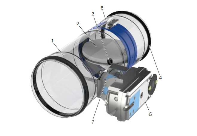
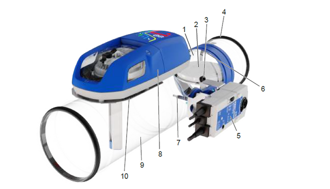
1 Casing
2 Fusible link
3 Damper blade with ring seal
4 Inspection access (12 mm)
5 Lip seal
6 Handle and damper blade position indicator
7 Travel stop for CLOSED position
8 Thermal release device
In the event of a fire, fire dampers shut automatically to prevent the propagation of fire and smoke through air ducts to adjacent designated fire compartments. In the event of a fire, the damper is triggered at 72 °C or at 95 °C (use in warm air ventilation systems) by a fusible link. The release mechanism is accessible and can be tested from the outside. One or two limit switches (optional attachment) can be used to indicate the damper blade position.
Nominal sizes | 100 – 315 mm |
Casing length | 400 mm |
Volume flow rate range | up to 770 l/s / to 2770 m³/h |
Differential pressure range | up to 1500 Pa |
Temperature range ¹, ³, ⁴ | -20 to 50 °C |
Release temperature | 72 °C or 95 °C (for warm air ventilation systems) |
Upstream velocity ² | ≤ 8 m/s with standard version; ≤ 10 m/s version with spring return actuator |
¹ Temperatures may differ for units with attachments. Details for other applications are available on request.
² Data apply to uniform upstream and downstream conditions of the fire dampers
³ For FKRS-EU in Ex version, see supplementary operating instructions
⁴ Non-condensing operation and without moisture entry via the outdoor air intake.
NS | ||||||||||
100 | 125 | 150 | 160 | 180 | 200 | 224 | 250 | 280 | 315 | |
A [m²] | 0.005 | 0.009 | 0.014 | 0.016 | 0.021 | 0.027 | 0.033 | 0.042 | 0.053 | 0.069 |
ζ | 1.71 | 1.08 | 0.76 | 0.67 | 0.54 | 0.44 | 0.56 | 0.45 | 0.36 | 0.28 |
Sizes: 100, 125, 150, 160, 180, 200, 224, 250, 280, 315 mm
Optimised low-leakage casing, up to leakage class C to EN 1751 with low differential pressure and low sound power level. Damper casing made of galvanised sheet steel, optionally galvanised sheet steel with powder coating RAL 7001, or stainless steel 1.4301. Damper blade made of special insulating material, optionally with impregnation. Corrosion protection according to EN 15650 in connection with EN 60068-2-52 Meets the hygienic requirements according to VDI 6022-1, VDI 3803-1, DIN 1946-4, EN 16798-3 as well as Ö-Norm H 6020 and H 6021, and SWKI.
Casing length 400 mm, for the connection to ducts made of noncombustible or combustible materials. Thermal release at 72 °C or 95 °C (warm air ventilation systems) with a fusible link or thermoelectrically with a spring return actuator, push button and indicator light (LED). Versions with a brushless spring return actuator for opening and closing the fire damper, also when the ventilation system is running and regardless of the nominal size, are particularly suitable for functional checks or daily shut-offs of duct sections. A spring return actuator can be retrofitted from the outside without modifying the linkage. Explosion-proof constructions for zones 1, 2, 21 and 22 with spring return actuator.
Special features| FKRS-EU | – | 1 | – | 7 | – | W | / | DE | / | 200 | / | TQ2 | / | SA | / | ZL10 |
| | | | | | | | | | | | | | | | | | | ||||||||
| 1 | 2 | 3 | 4 | 5 | 6 | 7 | 8 | 9 |
1 Type
FKRS-EU Fire damper
2 Casing variant
No entry: standard construction
1 Powder-coated casing, RAL 7001 (silver grey)
2 Stainless steel casing
3 Damper blade variant
No entry: standard variant
7 impregnated damper blade
4 Fusible link/thermoelectric release device
No entry: 72 °C release temperature
W¹ 95 °C release temperature (only for warm air ventilation systems)
B² with coated fusible link, 72 °C release temperature
WB² with coated fusible link, 95 °C release temperature (only for warm air ventilation systems)
5 Country of destination
Specify country code
6 Nominal size [mm]
100, 125, 150, 160, 180, 200, 224, 250, 280, 315
7 Accessories 1
No entry: without accessories
ER circular installation block
TQ2 square installation kit
WA2 Installation kit for mounting directly on walls and ceilings
WE2 Installation kit for installation away from walls and ceilings
GL2 Installation kit for flexible ceiling joint
TS2³ Rectangular narrow installation kit for dry mortarless installation in solid wood ceilings (twin installation)
8 Accessories 2
No entry: without accessories
Two entries required: accessories for operating side and for installation side
0 Side without accessories
A Cover grille
S flexible connector
9 Attachment
Z00 – ZEX4
¹ not with attachment ZEX1 - ZEX4
² only with attachment Z00 – Z03
³ For installation, a second FKRS-EU of the same nominal size with TS2 is always required
Order example: FKRS-EU-1-7-W/DE/200/TQ2/SA/ZL10
| Type | FKRS-EU Fire damper |
| Casing variant | powder-coated casing, RAL 7001 (silver grey) |
| Damper blade variant | impregnated damper blade |
| Fusible link/thermoelectric release device | 95 °C release temperature |
| Country of destination | Germany |
| Nominal size [mm] | 200 |
| Accessories 1 | square installation kit |
| Accessories 2 | Operating side: flexible spigot, Installation side: cover grille |
| Attachment | Spring return actuator 24 V AC/DC and module WA1/B3-AD |
Während in der Vergangenheit die Öffnungen für den Einbau einer Brandschutzklappe in eine massive Wand oder Decke exakt und nur mit geringen Toleranzen geplant und ausgeführt wurden, können die Weichschott-Lösungen sehr viel flexibler gehandhabt werden. So wird die Montage in vorhandene Öffnungen möglich, die umlaufend um bis zu 400 mm größer sein können als die Gehäuseabmessung. Exakte Planungen der Einbauöffnungen sind damit nicht mehr zwingend erforderlich

Owner: Mag. Benedikt Komarek
TROX-Products
Share page
Recommend this page
Recommend this page by sending a link by mail.
Share page
Thank you for your recommendation!
Your recommendation has been sent and should arrive shortly.
Contact
We are here for you

Please specify your message and type of request.
Tel.: +43 1 250 43-0 | Fax: +43 1 250 43 34
Contact
Thank you for your message!
Your message is send and will be processed shortly.
Our department for Service-Requests will contact you asap.
For general question regarding products or services you can also call:
Tel.: +43 1 250 43-0| Fax: +43 1 250 43 34
Contact
We are here for you
Please specify your message and type of request.
Tel.: +43 1 250 43-0 | Fax: +43 1 250 43 34
Contact
Thank you for your message!
Your message is send and will be processed shortly.
Our department for Service-Requests will contact you asap.
For general question regarding products or services you can also call:
Tel.: +43 1 250 43-0| Fax: +43 1 250 43 34


